
I didn't like how my trekking poles would vibrate upon striking the ground when I used them for trail running, so I decided to investigate and design something better and lighter.
In general, every physical structure has a natural frequency (frequencies) at which it vibrates when experiencing some kind of excitation, based on its material properties and physical structure. In the case of hiking poles, if the vibrational response is at a low enough frequency and the structure is not damped enough, there will be a brief vibration that can be felt in the hand and even heard every time the pole strikes the ground (each strike is a short but significant impulse applied to the pole). This was really annoying.
To solve this, I considered a few options:
All of these options are valid approaches to solving the issue, but because they have trade-offs, it was important to frame the problem in consideration of the primary design goals.
To make the poles easier to swing around quickly while running, we want to minimize their inertia. This means minimizing mass, and distributing as much of the remaining mass as close to the hand (pivot point) as possible.
I hate spending money
To make it easy to bring the poles with me and carry them around, I want to be able to reduce their (stored) length
To make these poles light, cheap, yet as stiff as possible, the obvious material choice was generic carbon fiber tubing. It has an insanely great stiffness-to-weight ratio, has better damping characteristics than metals, and most importantly: is very cheap and easy to source.
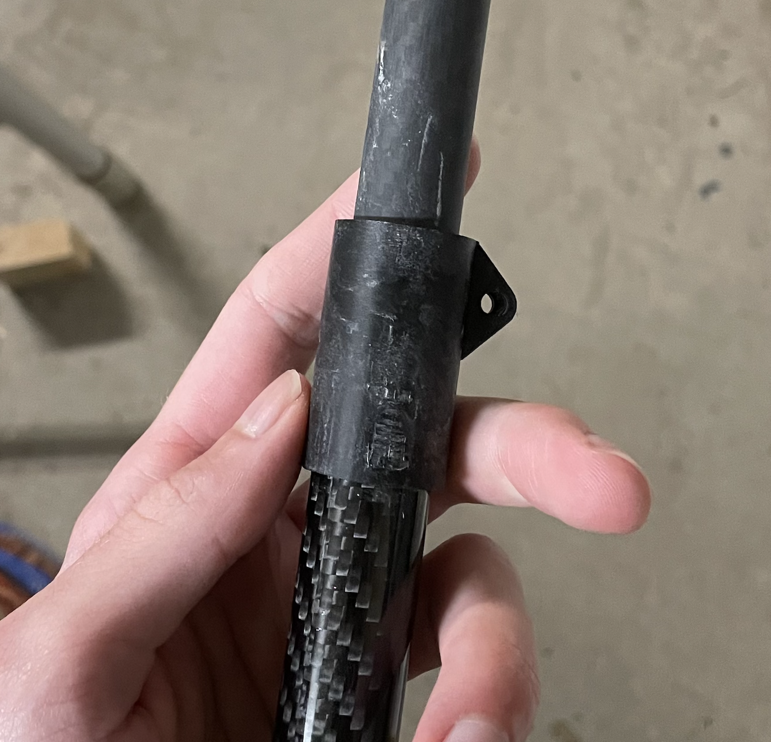
This is where the experimentation really started. Whacking models into ANSYS for hours makes me want to gouge my eyes out, so I decided to opt for the much faster and more practical method of "just sending it". I'm still working on this part, but I have a direction. There were a few different options I was considering for the architecture of these poles, but the most promising ones were to try either a telescoping design, or a design that relies on a few tube sections that are assembled together using couplers and a tensioning line on the inside of the tubes.
Because I had some concerns with stiffness of the connective points in the case of the folding tensioned idea, I tried the telescoping design first. After about an hour of trying to wet sand down the carbon tubes so that they would slide nicely, I decided that this was a fool's errand because it is not very repeatable manufacturing-wise due to tolerances of the inside cylindrical surfaces since I'm using cheaper carbon tube. From there, I moved on to the tensioned design idea, which seems to be popular in the hiking pole world anyways.
Mostly, I need to just sit down for a few hours and whack out some CAD for:
Then, after some prototyping and testing, I need to:
Will keep this page updated as I make progress.
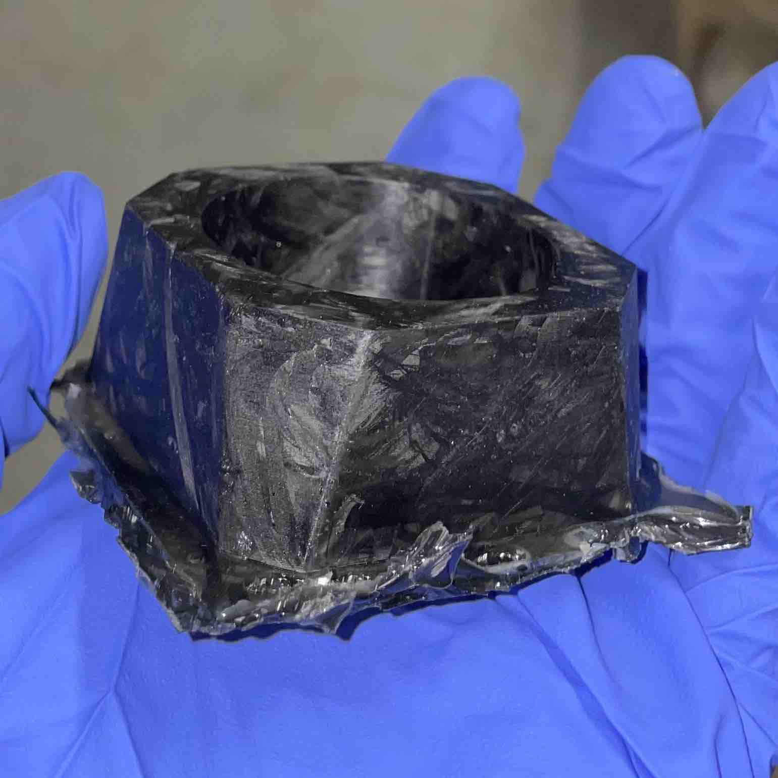
Because I have a minor obsession with composite materials, molding, and making cool materials in the laziest way possible, I went to the nonsense factory and did the laziest carbon fiber molding possible.
I had a relatively thin-walled design made from an earlier design study project (design of a "cyberpunk" candle holder), which would have been a great candidate to try to injection mold just as a test piece. Therefore, I decided: Why not try to mold it out of "forged carbon"? After all, forged carbon is just a fancy term coined by Lamborghini for "I smashed a bunch of carbon fiber together quickly and cheaply", since "we slapped something together" doesn't sound very fancy.
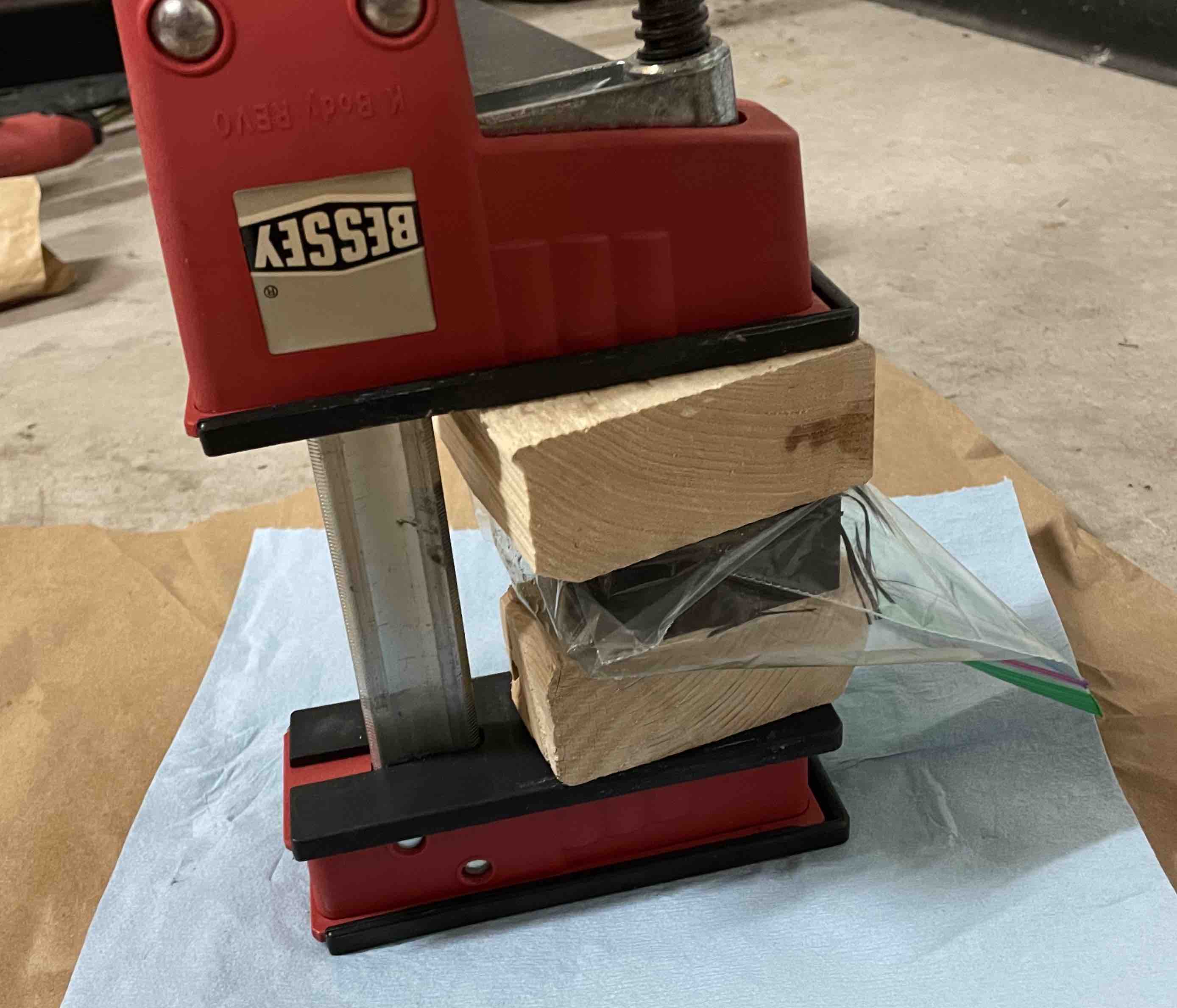
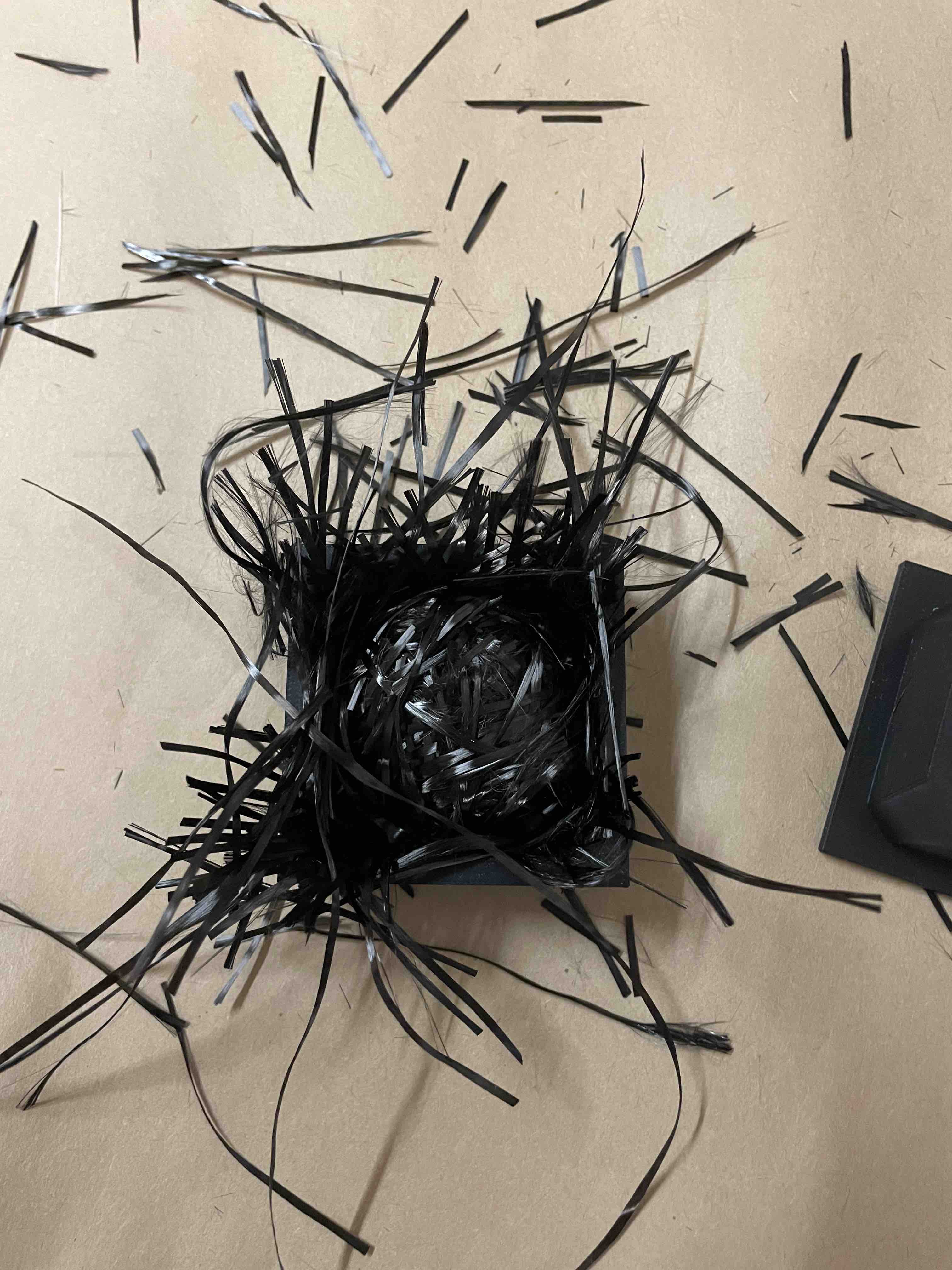
To actually get this thing together, I did the following:
I was actually quite pleased with the result considering how little effort I put in. It was a bit sloppy and non-uniform, partially because I had struggled to cram the mold with the strand lengths I had cut, but I'm happy with the end result.
I'm definitely going to try this again. To quote the algorithm messiah Superfastmatt, you gotta do it wrong the first time to do it (more) right (basically a law of physics). To do it better next time, I'm considering the following:
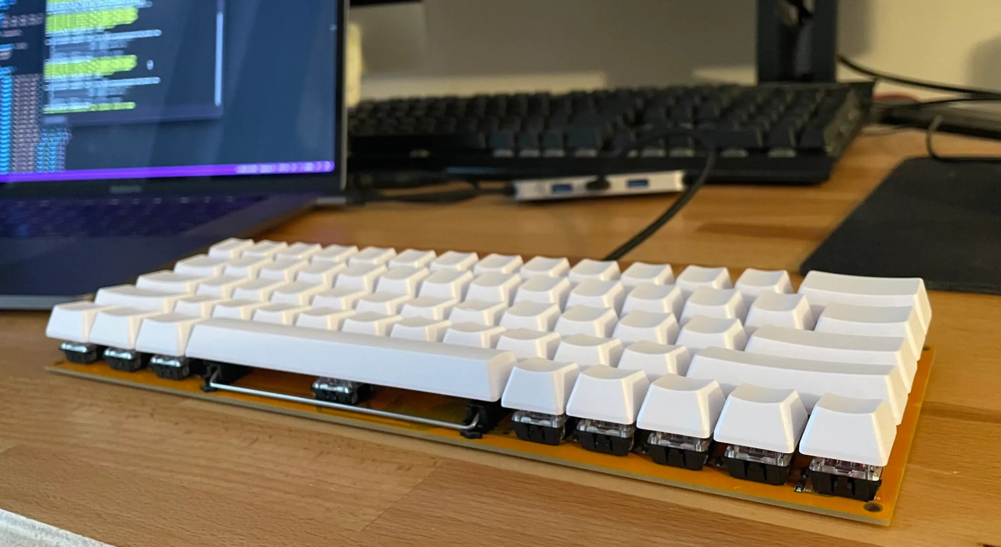
I wanted to make a cost effective mechanical keyboard and didn't really like the designs of any of the ones that were available at the time, so I decided to make one myself. I also wanted to try out an integrated product design project, so this was the perfect candidate.
I had been considering getting a 60% mechanical keyboard just to have something compact that I could bring around with me to plug into my laptop. I also wanted to take a shot at defining and design a product I would actually use at length - I have a real passion for physical products that have strong design, focused on utilitarianism while remaining minimal, so this was a great opportunity to do just that.
From the beginning of the project, I felt confident in the design direction I wanted to take. There were still some unknowns so to constrain the design space, I laid out some basic success criteria:
To accomplish the functions laid out above and constrain the project further, the next logical step was to define exact technical specs for the keyboard:
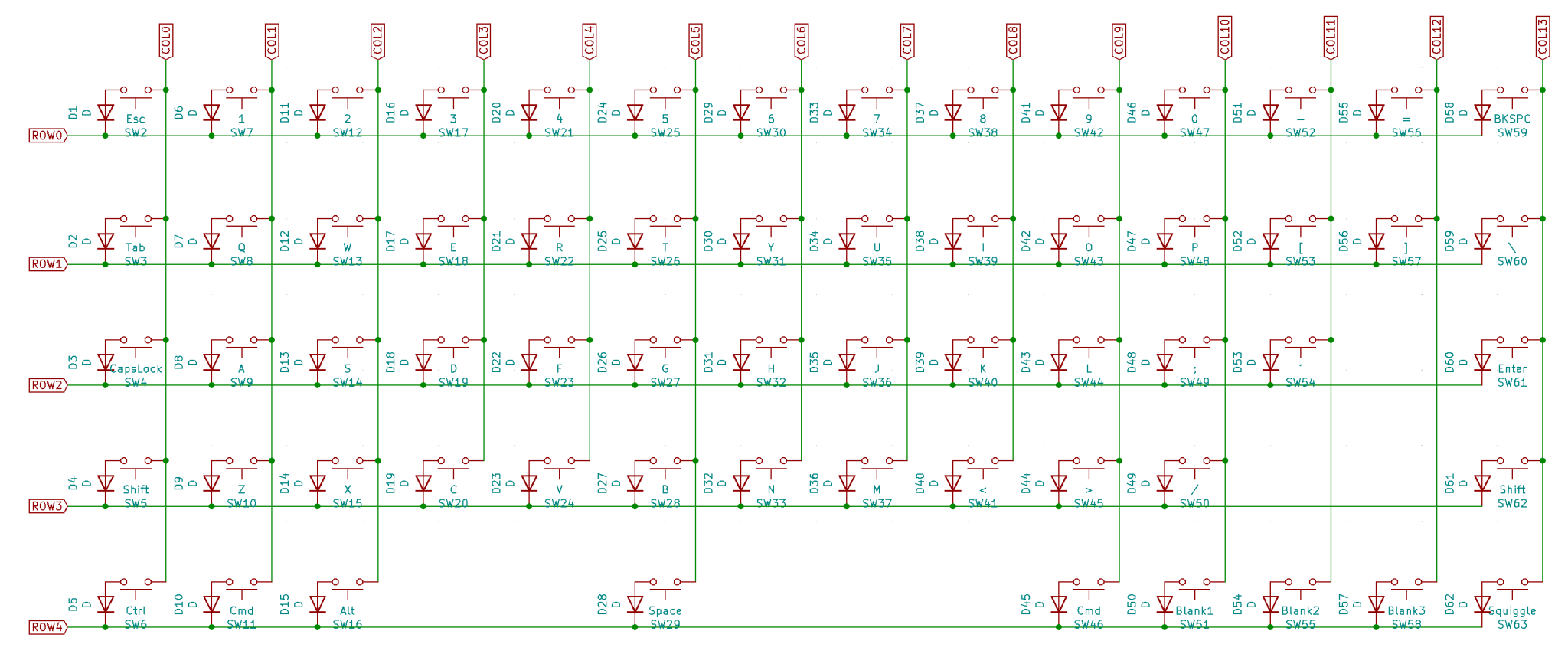
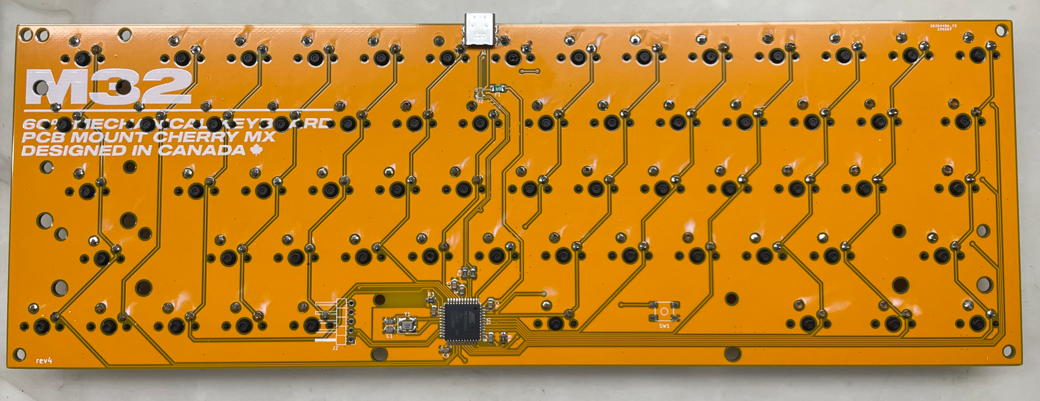
The next logical step was to design the keyboard PCB based on the layout. After some brainstorming, I came up with this:
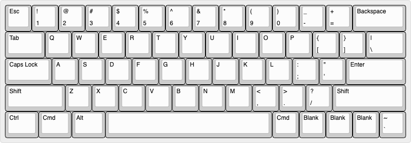
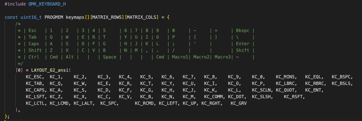
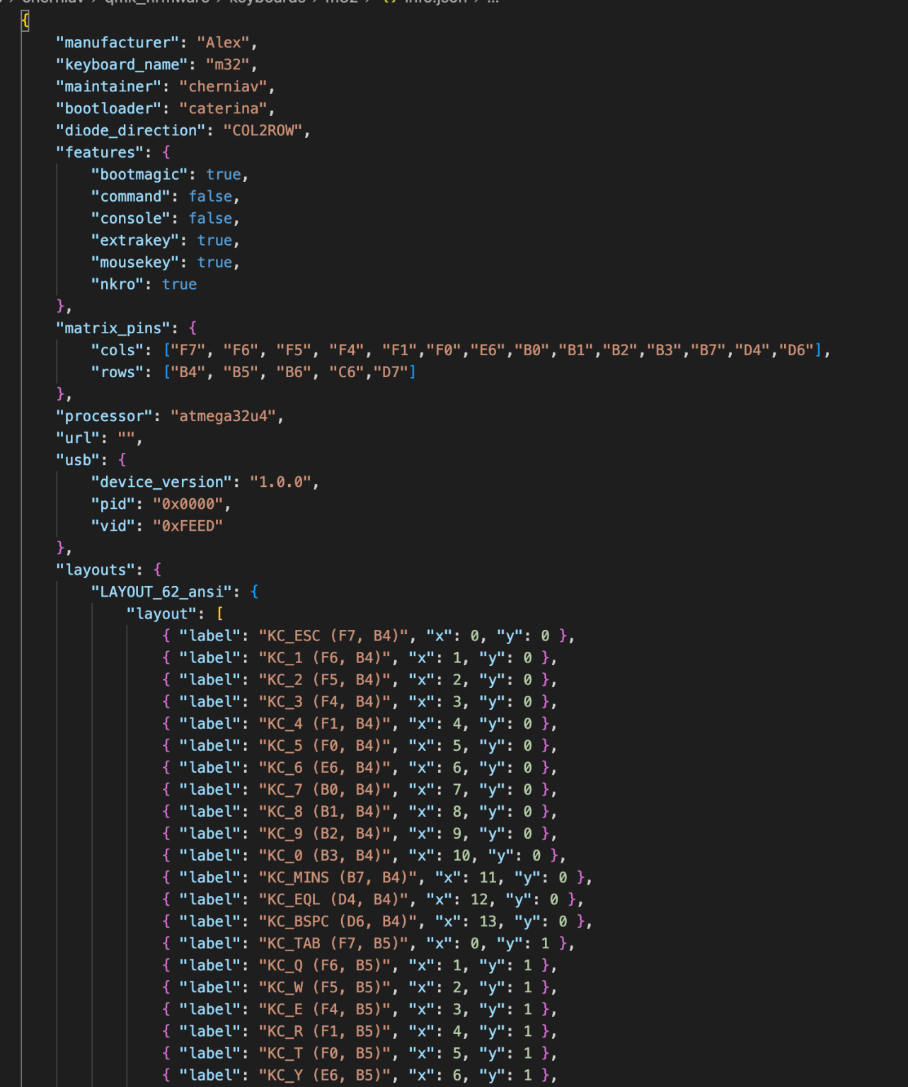
The biggest customization here was replacing the keys on the bottom right with generic macro keys. I find that the typical "media", "alt", and "ctrl" keys are not really useful for me, so why not keep their definition open. Next, I needed to determine the electrical row & column layout that would form the basis for the keyboard’s scanning matrix:
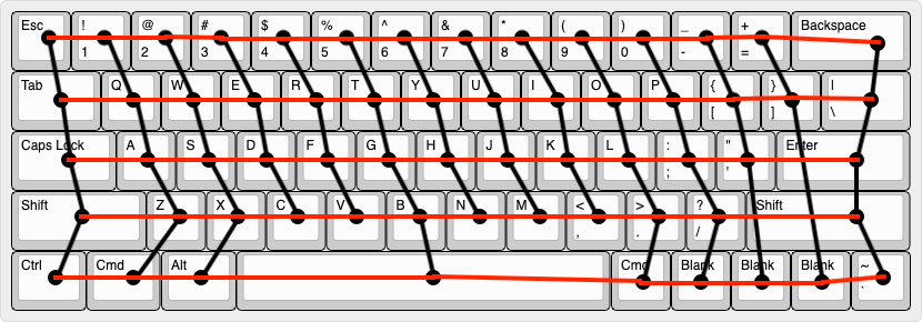
I then translated this into a schematic as follows:
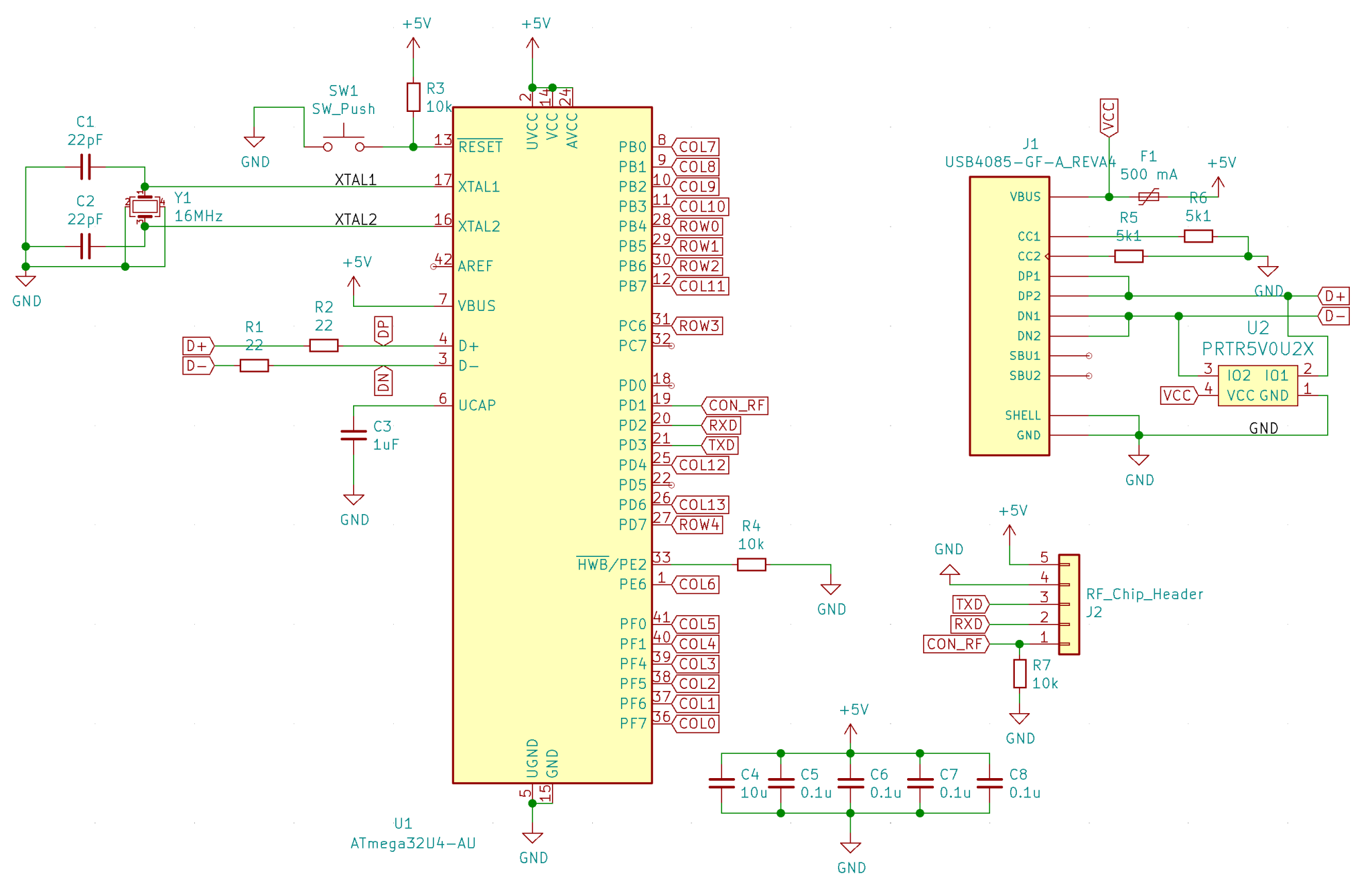
And then a PCB layout (this took several attempts):
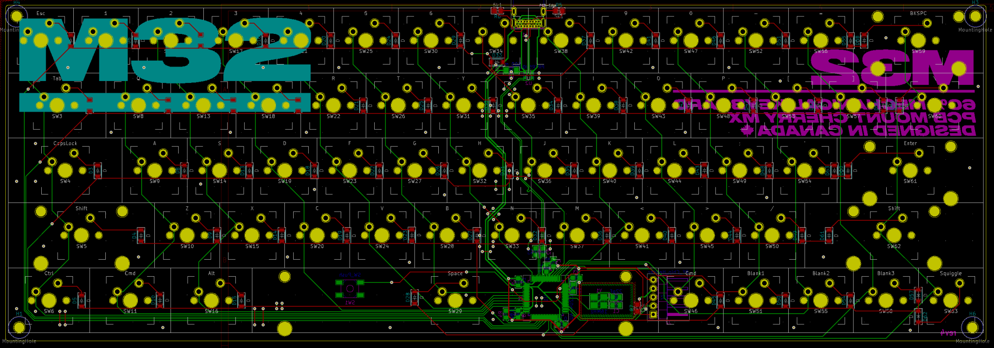
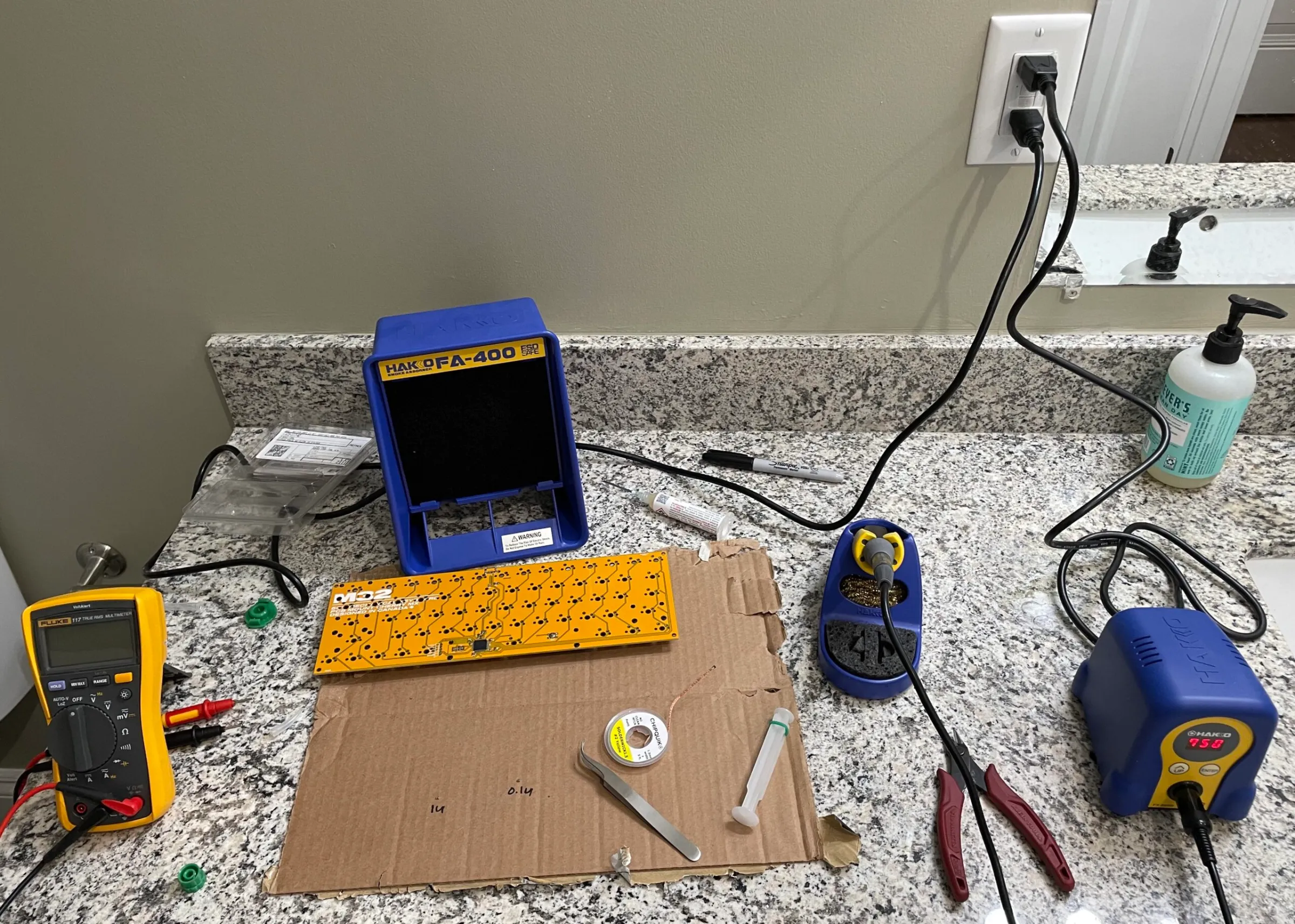
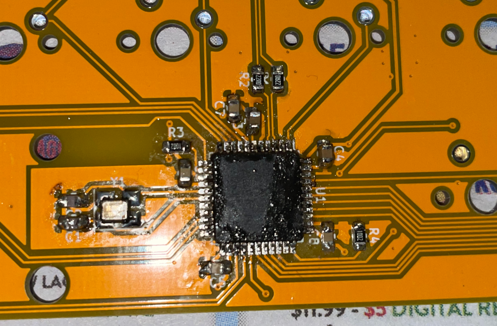
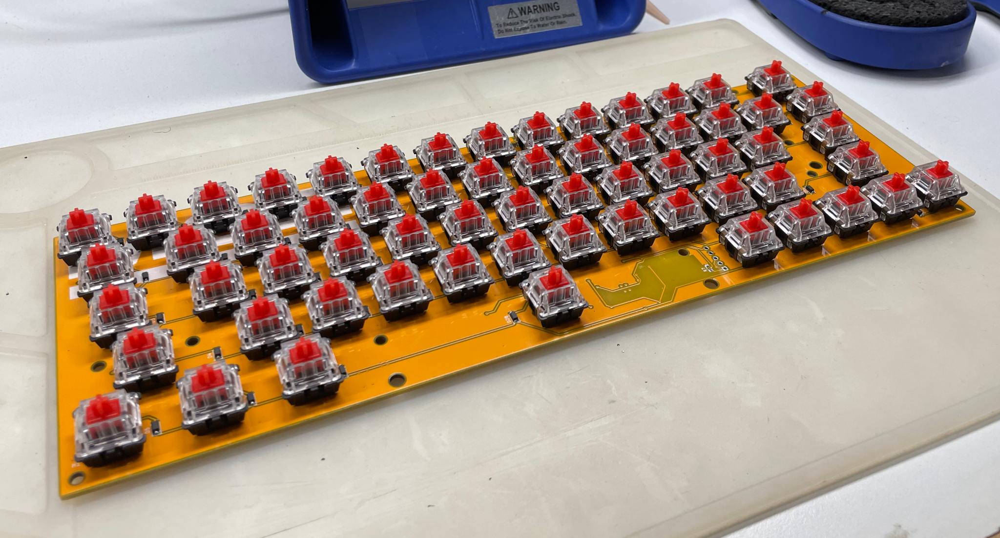
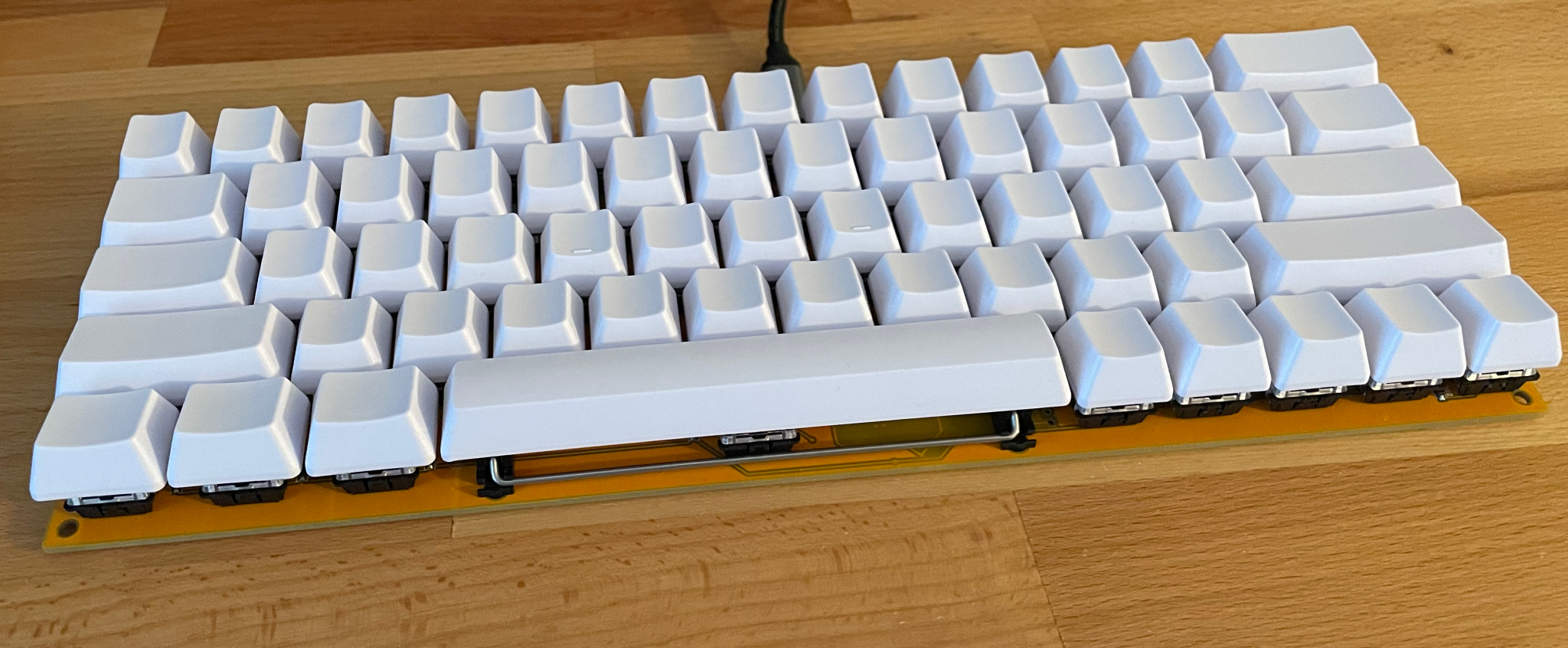
After verifying the design & ordering the PCB and its components, it was time to build (If you want to see my super simple monkey code, see at the end).
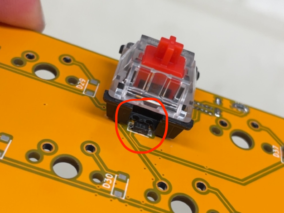
The code was really just a bunch of markup files that ended up being complex into a hex by the open-source QMK compiler through a command line.

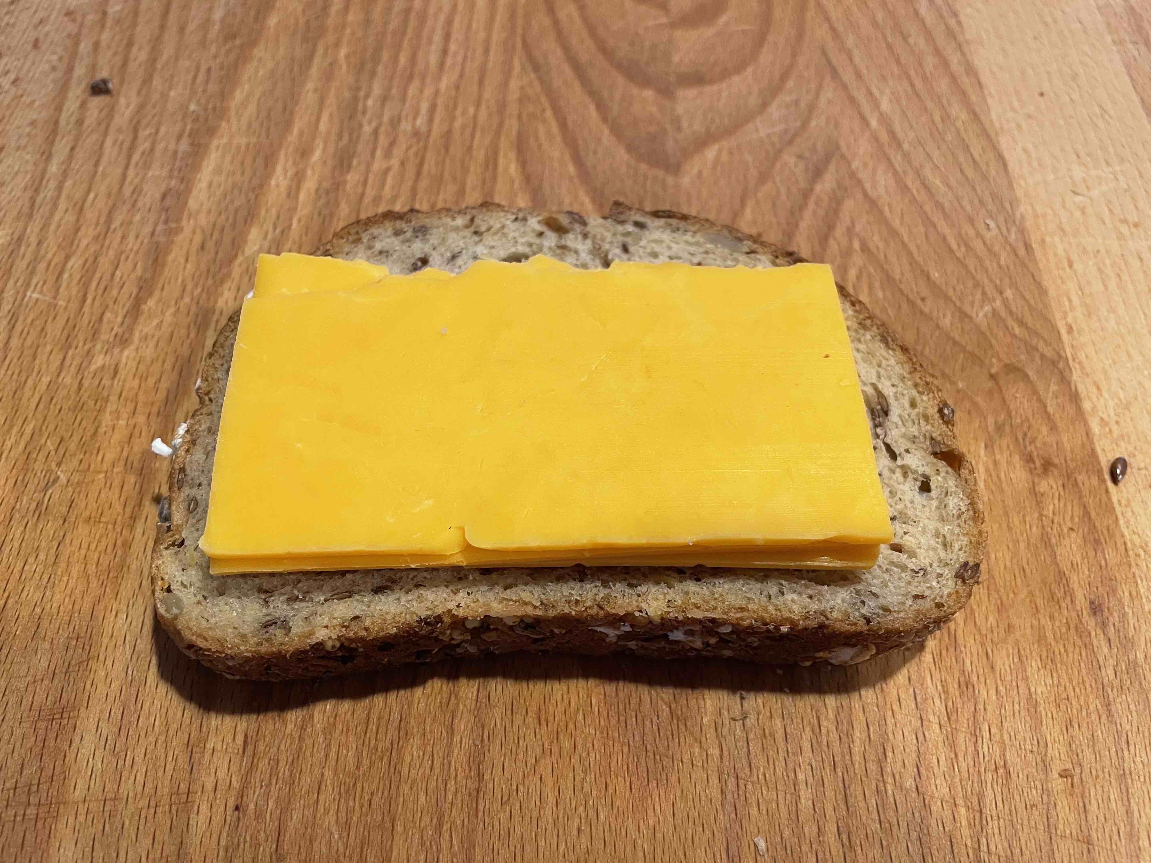
Grilled cheese is delicious. It is even more delicious when you can make it in 5 minutes. Here are some instructions to make it in 5 minutes. What are you waiting for? Go make yourself a grilled cheese! You know you want to
I am not responsible for any taste offences you may commit in the process of fabricating this grilled cheese. If it doesn't taste good, then it is clearly out of spec (this instruction is for making in-spec grilled cheeses only). Check the instructions, and / or add more cheese, and if that doesn't work, cry a bit then apply some first principles reasoning.
Assemble the cheese onto your first slice of bread. Make sure the cheese is solidly within the boundaries of the crust so that it doesn't exit its enclosure during heating. Fold it in half if you need to (as I have done).
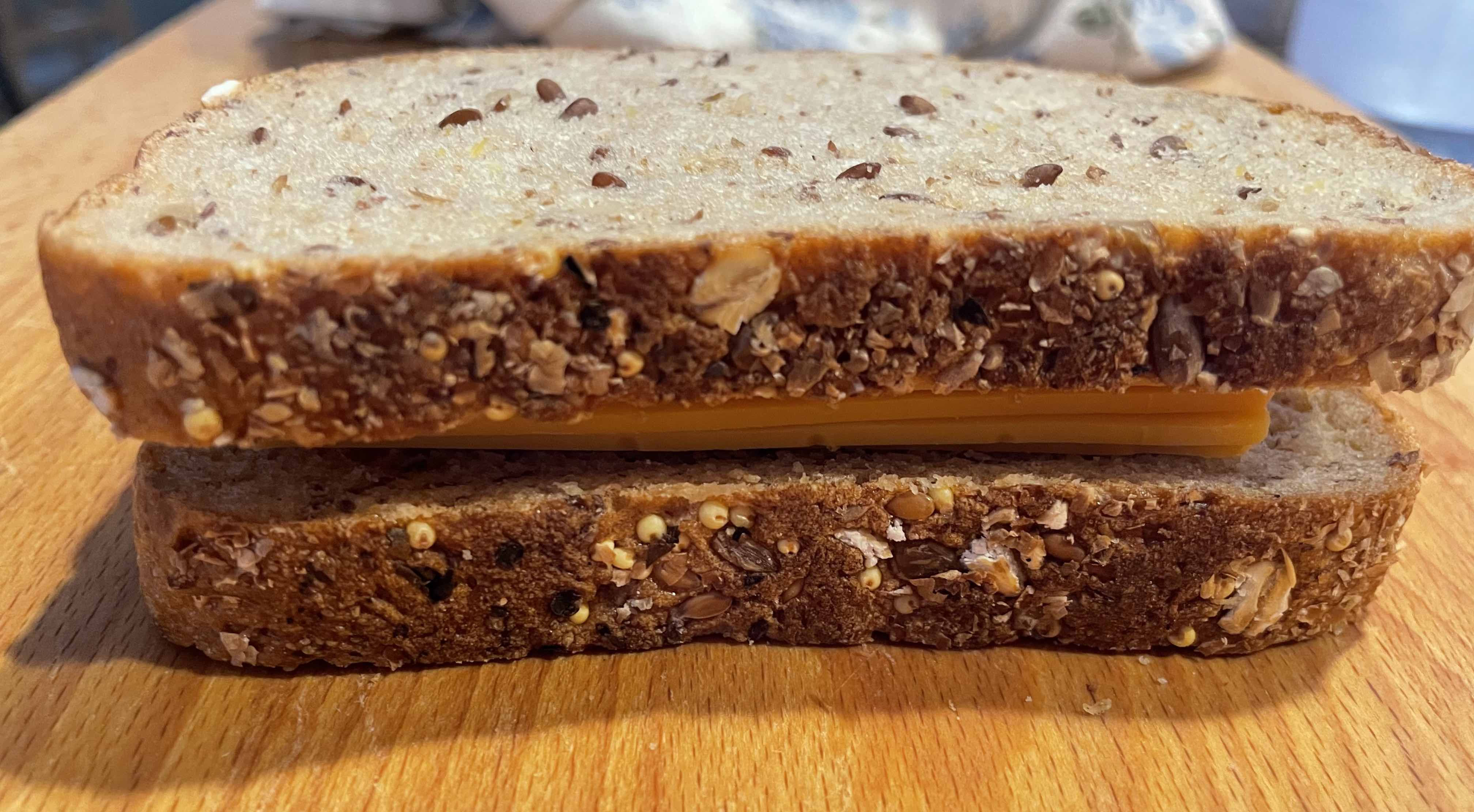
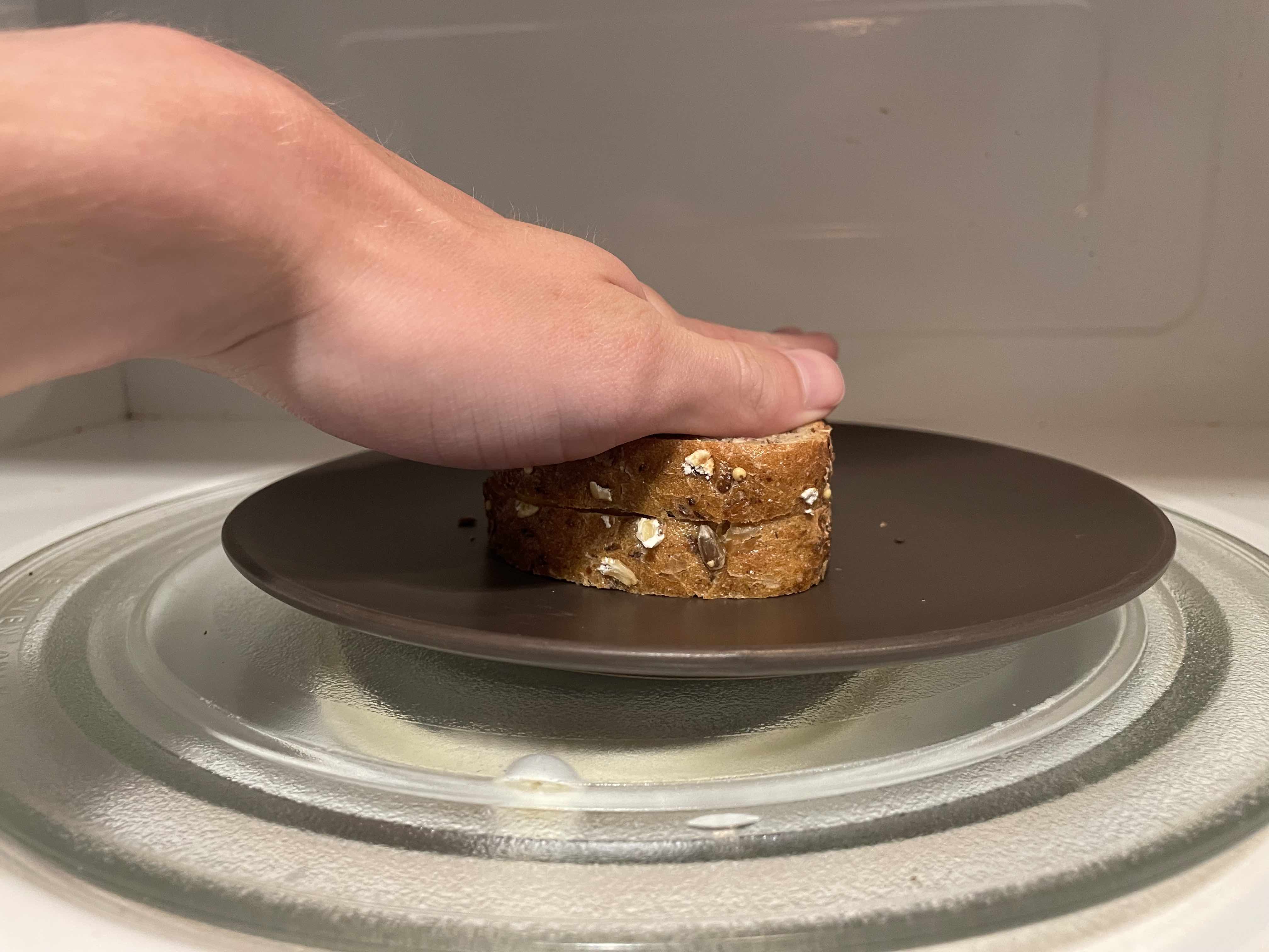
Then assemble the second piece of bread on top of the cheese stack. Apply vertical force with hand to slightly compact + stabilize the stack (pre-load the bread) if necessary.
Place your stack into the microwave. Microwave for a bit until cheese is melted and bread is very sweaty.
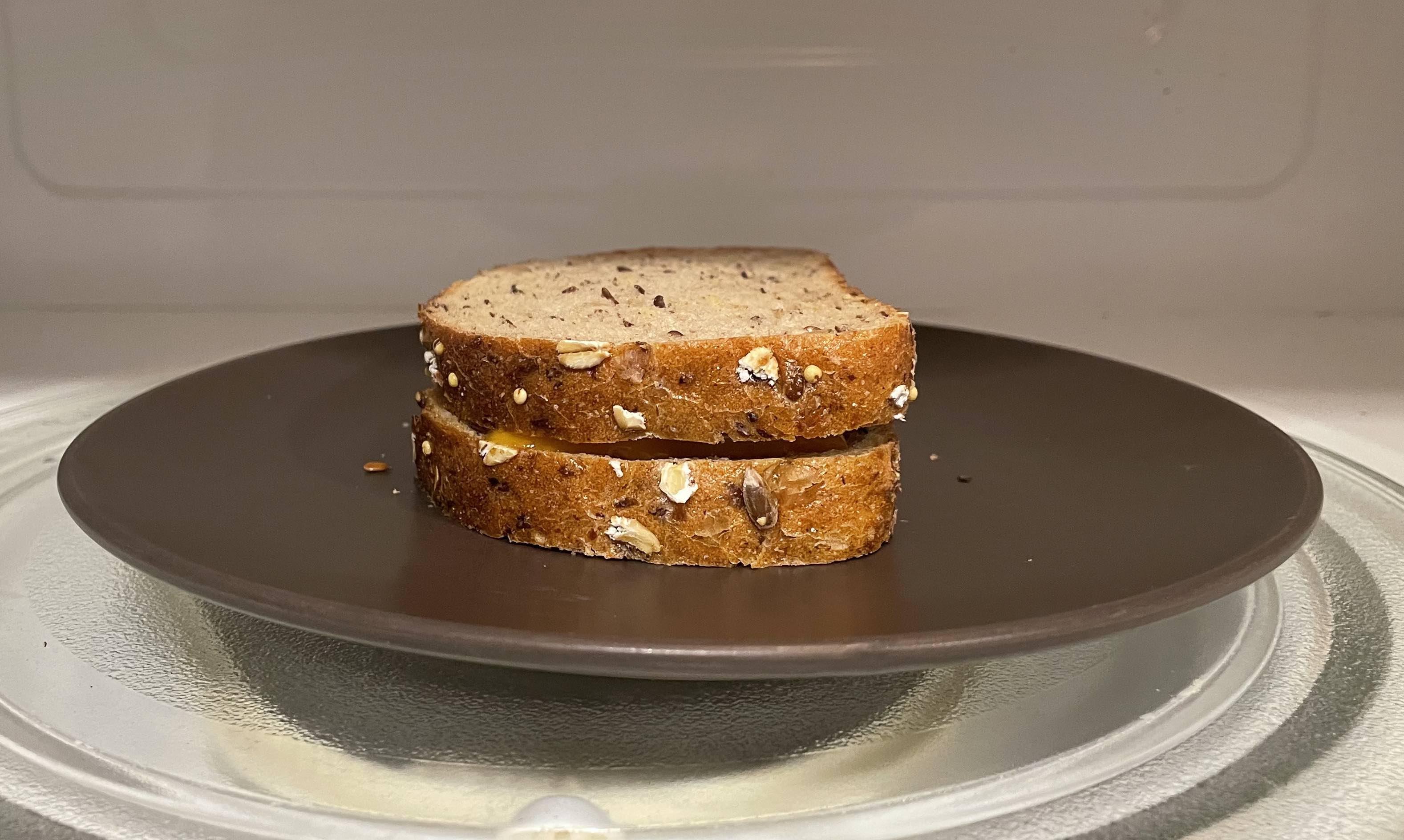
If there is a bit of a gap between the two pieces of bread after this, make sure to press the stack together to make sure the bread and cheese assembly preload is within spec before taking out of the microwave.
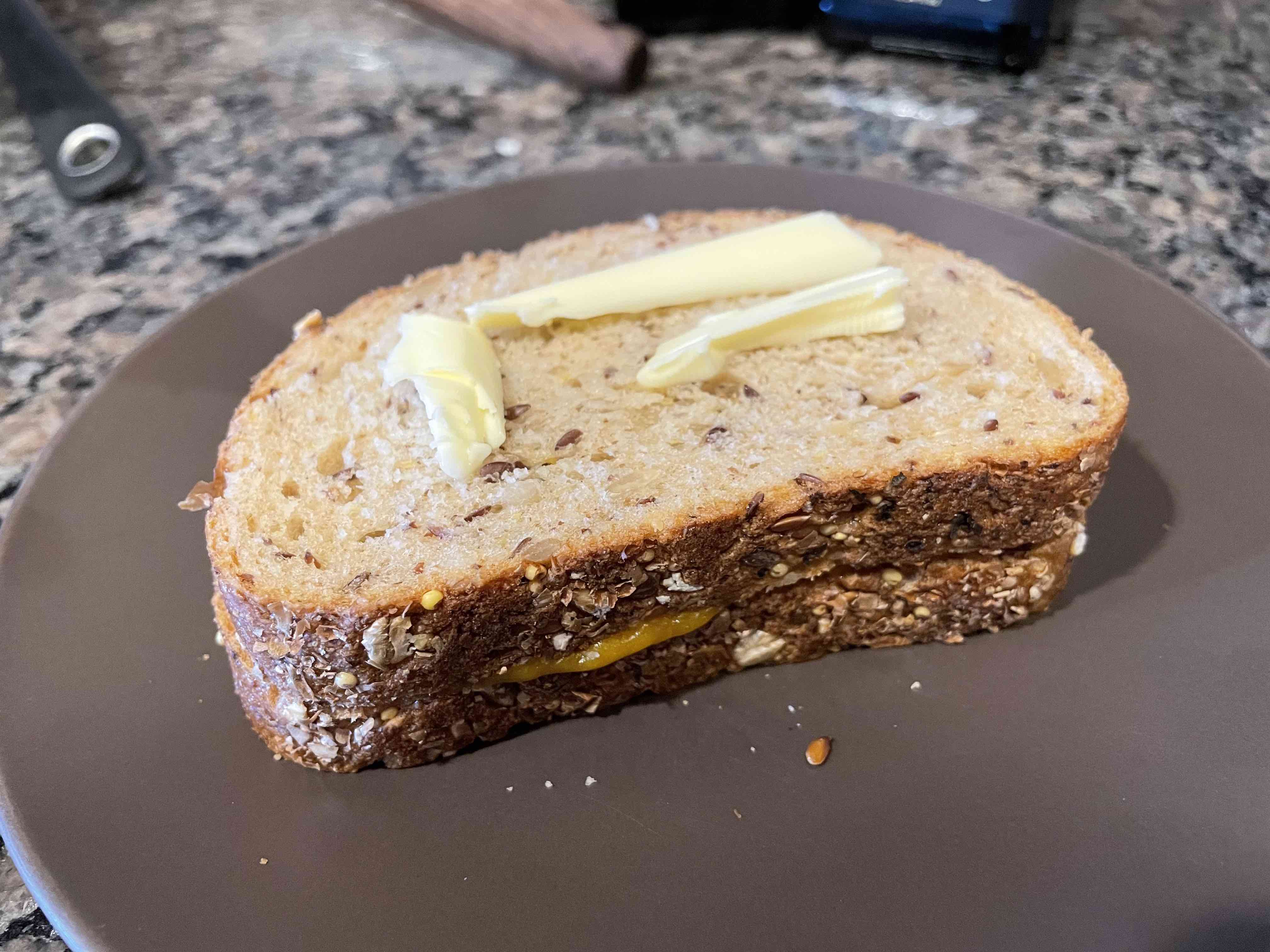
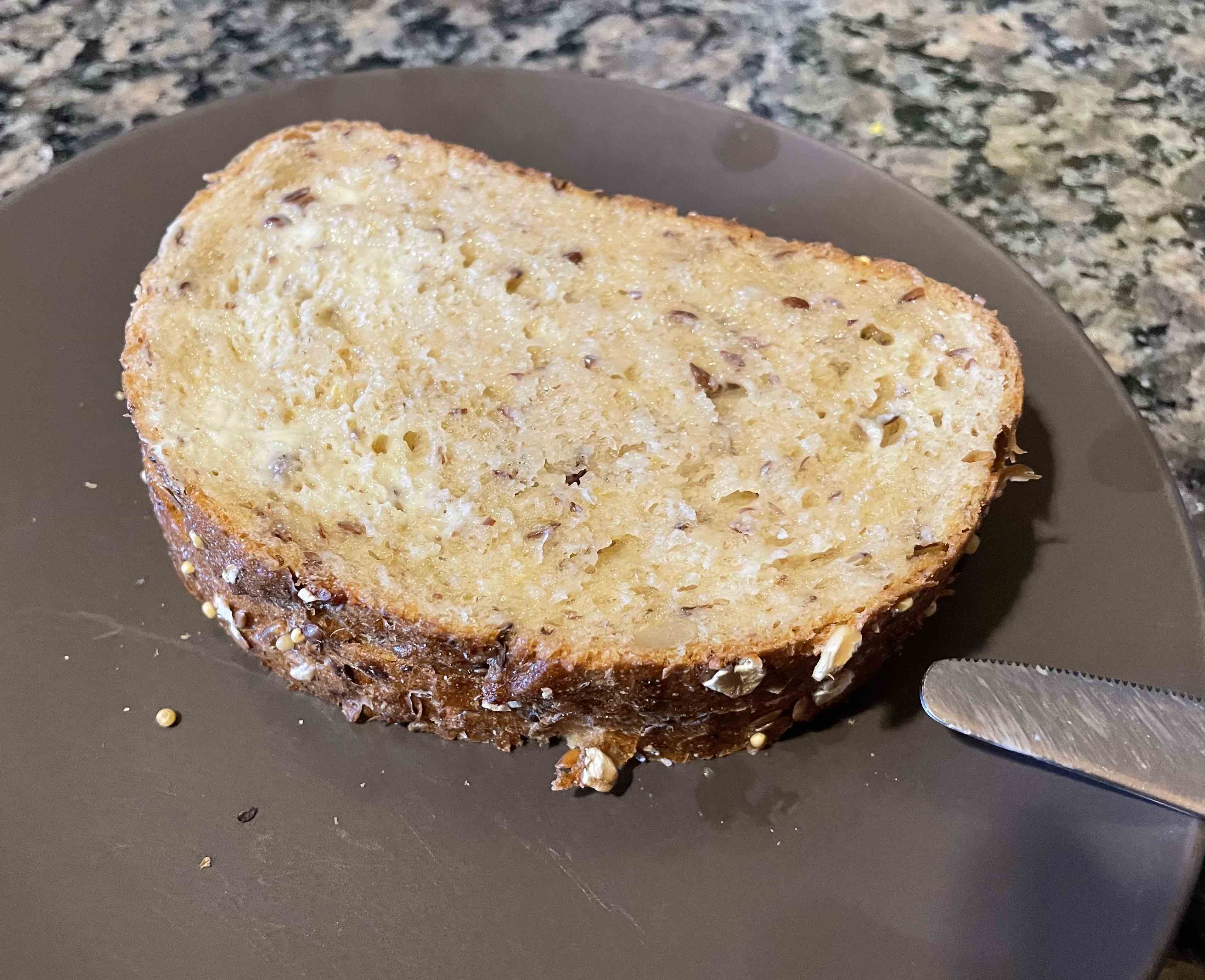
While the bread is still hot and sweaty, quickly and liberally apply your salted butter to both sides of the bread. Make sure you get a solid coat of butter: This is very important.
Make sure your CAST IRON pan is nice and hot. You're not melting the cheese: You're just toasting both sides of the buttered up bread. If you don't use CAST IRON your grilled cheese will be out of spec. Just toss the grilled cheese on the pan, wait for the first side to get nice and golden brown, then turn it over and do the same.
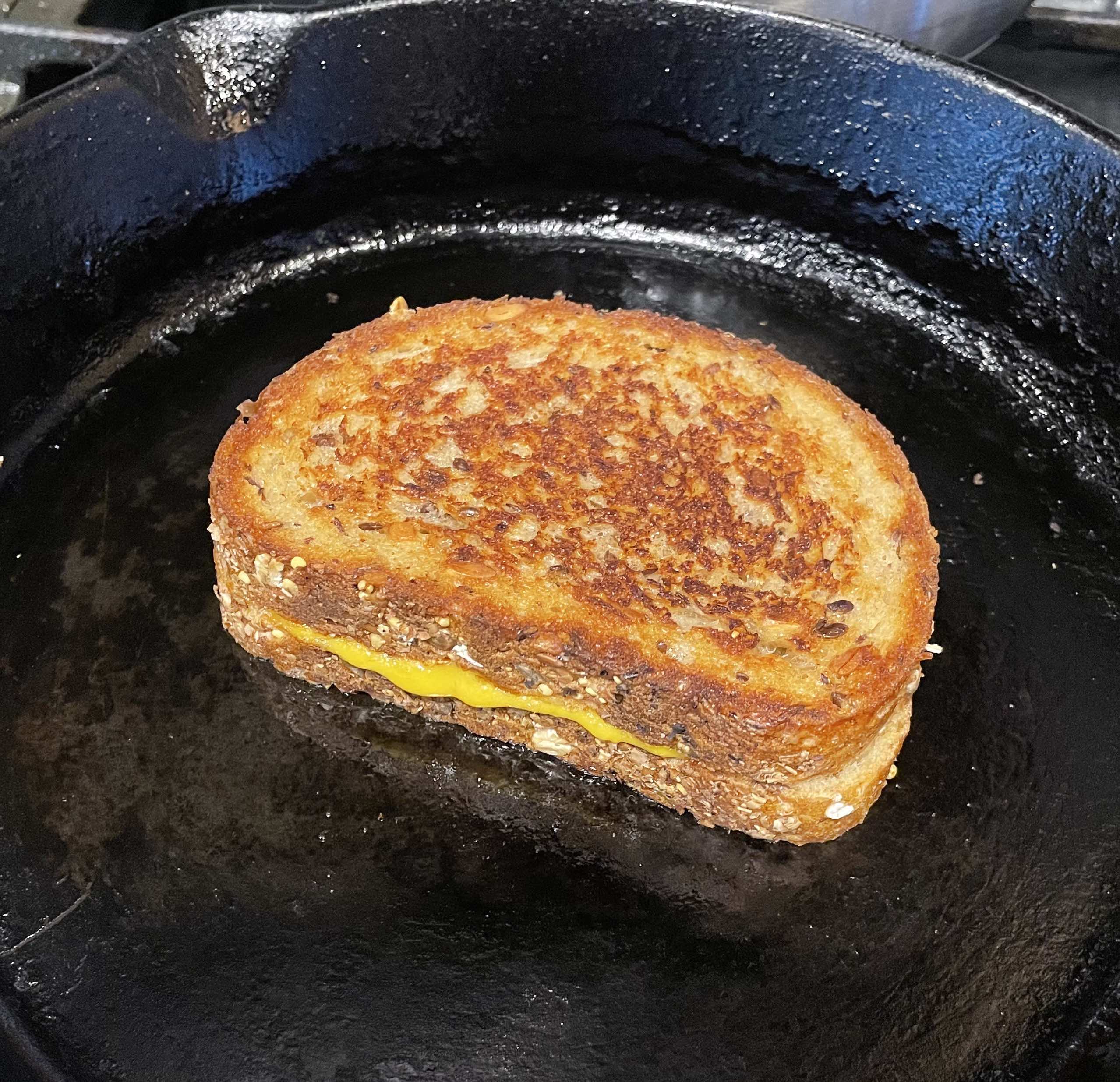
Once toasted, take the grilled cheese off the pan and plate
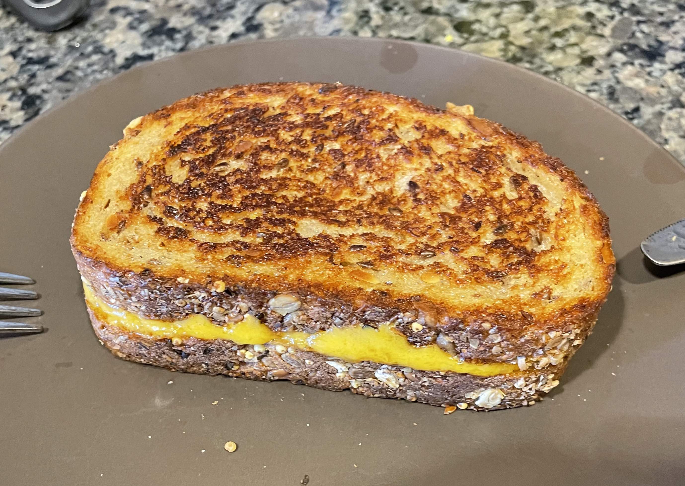
Congrats! You can now bless your taste buds with the grilled cheese you made using my amazing method (post- night out friendly).
If you used a pan that was not cast iron, you may now sit and eat your grilled cheese in shame while you consider how your life choices led to you not using a cast iron pan to make your grilled cheese.
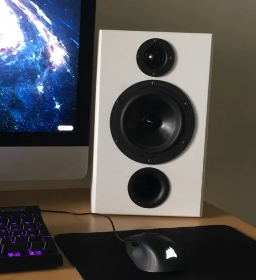
I wanted a pair of desktop speakers, but didn't really like the design of any of the ones I could buy at the time, so I made my own. Accidentally made them massive due to a severe case of CAD goggles.
Here you can provide more context about why you started this project or what problem it aims to solve.
Like many others, I listen to music religiously. I find that it enhances how I experience the world so it's something I've always connected with. Because of this, I'm picky about sound quality. I'm also fairly picky about design - I was looking for a minimal but tech-y aesthetic similar to retro speakers I had been looking at for inspiration.
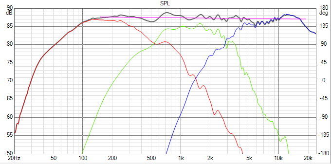
Because of the vast selection of speaker drivers available, I had to first figure out what I wanted to get out of this project. I knew I liked a flat frequency response from the kind of headphones I use at home. I also knew I wanted a fairly good bass response without having to add a subwoofer under my desk, so my selection narrowed down to larger mid-range drivers.
Based on pricing of available Amplifiers and Crossovers, I ended up choosing a 2-driver / speaker (4 total channel) speaker architecture. From there, I ended up choosing an 8-ohm 6-inch driver (Dayton Audio RS150P) based on my requirements. The size is a bit overkill, but better to oversize than to undersize in my opinion. For the high-range tweeter, I chose an appropriately sized 1" soft dome driver (ND25FA) as it had great compatibility with the midrange driver.
I made sure to select the drivers based on their frequency response compatibility using a software called VituixCAD. I was initially planning to build a physical crossover circuit using low / high pass filters, but this didn't end up being necessary since I used a digital crossover.
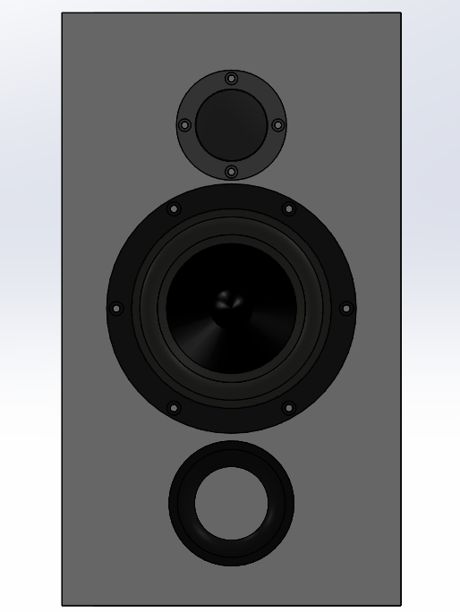
Once I had the driver selected, I had to design the parameters for the speaker cabinets - Important because speaker and port hole size influence how the air behind the speaker drivers moves, therefore influencing sound output. To do this, I used a web app called Speaker Box Lite. With this app, I calculated the parameters I needed to design for based on the drivers I had selected, extracting volume and port length required to match my desired frequency parameters.
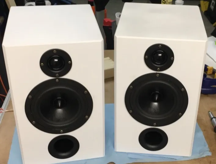
After design parameter determination, it was time for my favourite part: Physical product design. For my design, I chose simple white cabinets with bevelled edges. I liked the simplistic polygonal look, emulating retro speaker aesthetics I have always liked.
I didn't really take any pictures of the manufacturing process, so here's kind of a brief explanation of how I did it:
I built the speakers out of MDF sheets because they were easy to source and work with, and also because their density would help with damping non-nominal structural vibrations due to air movement. One main issue with MDF though: Because of its porosity, it loves to absorb paint, so I really had to prep the surfaces well with shellac before painting, done after cutting out the boards, holes, and gluing everything together. If I had to paint MDF again, I think I would opt for some kind of plastic coating instead to make it less complicated and more durable.
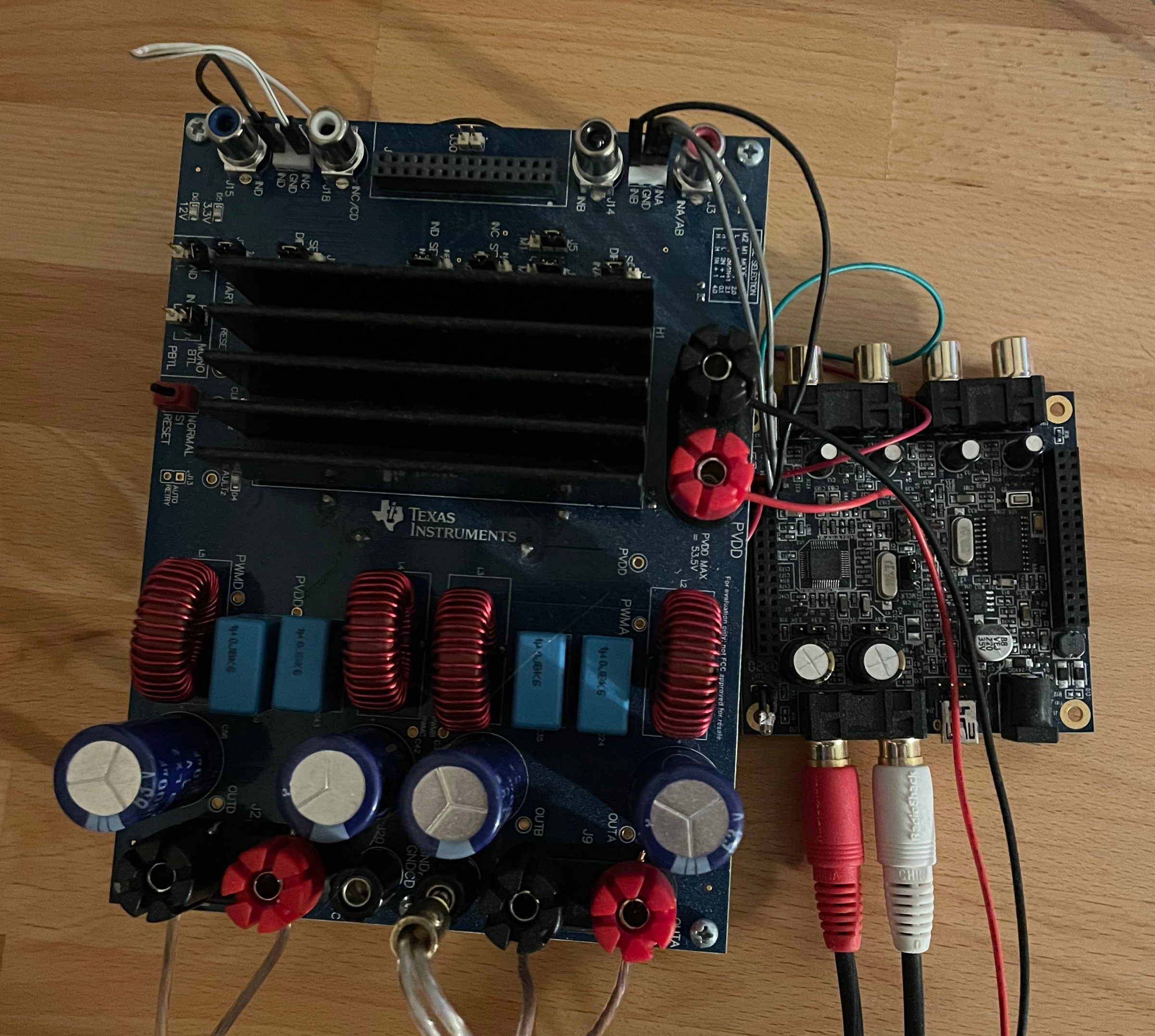
To actually drive the drivers properly, we need an amplifier. For mine, I chose a TPA3255-based Class D amp just to go with something good the first time. Originally, I bought a board by an audio company, but when it arrived I realized it was differential, so I could only output to two drivers (Lesson #1). I tried to rework the board by cutting some traces and re-soldering some wire bridges, but during some power supply-powered diagnostics, the MCU and some other components ended up getting fried because the person that was looking over the board for me touched a bare trace to an exposed MCU pin (Lesson #2) – Good way to learn to be careful about this kind of thing I guess. I ended up just using a spare TPA3255 EVM from TI themselves, and although the form factor is not great, it works perfectly.
The crossover I ended up using was by MiniDSP. I was able to make all of the frequency response tweaks I wanted to make through VituixCAD earlier, except with basically unlimited customizability and a great price tag for what it does. The digital future is awesome.
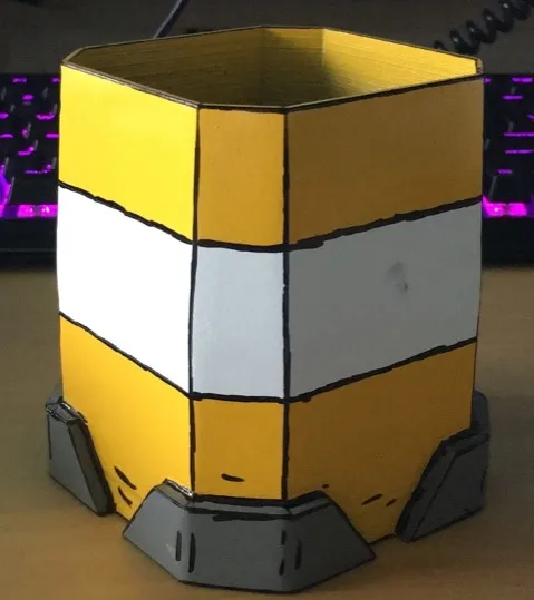
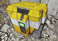
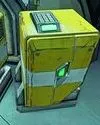
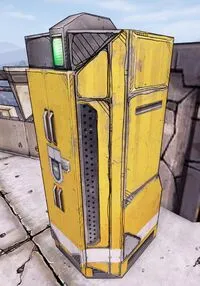
I wanted to try my hand at a bit of industrial design inspired by an art style from one of my favourite video games, Borderlands 2, and I also needed a pen holder, so I made one.

Because the design was based on a specific art / design style, I drew heavily on existing designs for inspiration to generate this new one. To do this, I asked myself, “If this fictional company made a pen holder, what would it look like?”. Going through this process was a great learning experience in aesthetic design intuition, which is something I think most engineers sorely lack.
After generating a 3D model I was happy with, it was time to 3D print it. This was back in the good old days when printers were still unreliable for larger prints, so this was a bit of a challenge at the time. The simple geometry reflects this: It had to be easy to print. After printing, I needed to smooth the surface so that I could paint it. For my purposes, I used Smooth-On’s XTC3D Performance Coating to lower the visibility of layer lines and other printing artifacts. After this, just had to do some light sanding, and then it was ready to spray paint.
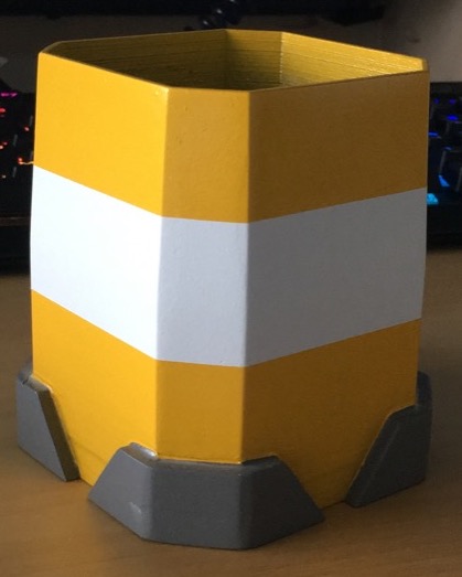
After painting the pen holder, I traced "particle" and "edge" accents to enhance contrast between the colours and reflect the cel-shaded art style of Borderlands. Though it was just sharpied on, I was quite happy with the end result.